Guide · Setup page · CAN4
The CAN4 setup page
Every setting on the CAN4 is made on its own setup page, served by the module over its own WiFi and opened in a phone's or laptop's browser. This guide goes through the page control by control: how to get on, the first-run question, the four tabs, and what each message means. The setup guides for each ECU say which of these settings that ECU needs.
Written from the page as firmware 0.2 serves it, October 2026. The screens are the page's own, drawn by that firmware at phone size. The page has been tried on one iPhone so far, on a development board, and not yet on a finished unit.
00What you need
- The CAN4 wired and powered with the ignition. Wiring is in the setup guide for your ECU and the datasheet.
- A phone or laptop with WiFi. The page needs no app and no cable.
- The WiFi password printed on the module's label.
- For any change to the bit rate, identifiers or frames: the ECU on and the bus connected. A bus change is kept only once something on the bus acknowledges it.
Getting on
01Join its WiFi
- Switch the ignition on. The module's WiFi network,
CAN4-followed by four characters, is up for 5 minutes after power-on. It stays up while the setup page is open and for 5 minutes after it was last open. Once it has closed it opens again at the next power-on, so switch the ignition off and on. - Join the network with the password on the module's label. Each unit has its own, WPA2.
- Open the page. A phone may open it by itself, in a sign-in window, when it joins. If it does not, open the phone's WiFi settings and tap the network, or go to
192.168.4.1in the browser. On Android, if the page does not open, tap the network's sign-in notification or turn mobile data off.
The sign-in window is not a full browser. On Android it cannot pick a file, so the Unit tab hides the firmware and backup file controls there and says so; on either phone a download may do nothing. For those, open http://192.168.4.1 in Safari or Chrome while the phone is on the module's WiFi, with mobile data off on Android. Everything else works in the sign-in window.
02Across the top
The bar at the top shows CAN4, the firmware version, and a chip with what the module is doing on the bus. The same chip is on the Bus tab, 09, with its advice. Under the bar, messages appear while they apply:
- No answer from the module
- The page has heard nothing for a few seconds, so the readings it shows are old. The phone has usually left the module's WiFi, or the WiFi has closed. Rejoin it; the page picks up again by itself.
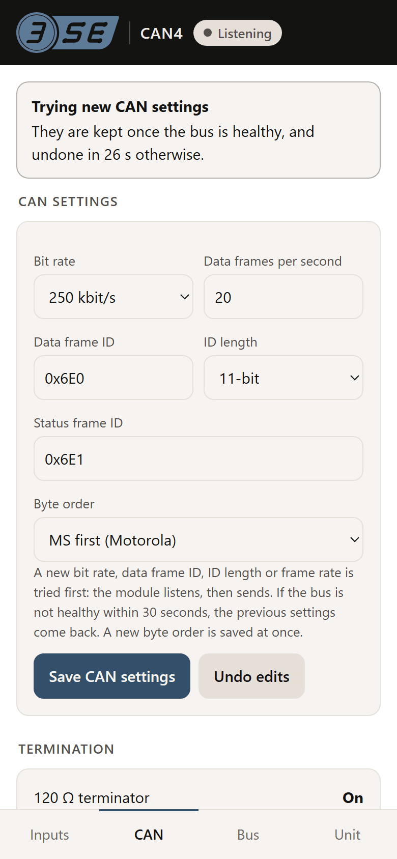
- Trying new CAN settings
- A new bit rate, identifier, frame length or rate is on trial, with a countdown. It is kept once the bus is healthy, and undone when the countdown ends otherwise.
- A CAN change was undone
- The bus was not healthy within 30 seconds of a change, so the settings before it are back. The CAN tab shows the settings in use. OK clears the message.
- New firmware on trial
- An update is running and is kept once the bus is healthy. If the bus is not healthy before its countdown ends, the module goes back to the version before.
- The 5 V sensor supply has tripped
- A sensor cable's red 5 V conductor is probably shorted to ground. The supply comes back by itself once the short is gone. All four inputs share it.
- The 5 V reference is not being measured
- The module has had no good reading of its own 5 V lately, so it works the readings out as if it were exactly 5 V. A cold thermistor may read a few degrees out until it is measured again.
- Not sending
- The module has stopped transmitting. The message carries the Bus tab's advice; see 09.
03The first question
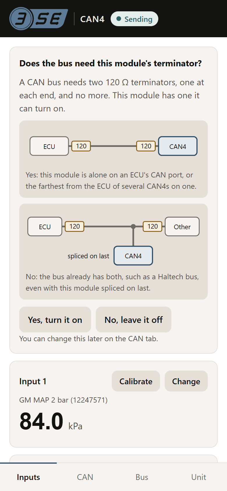
A new unit, or one whose settings were reset, asks one question at the top of the Inputs tab: Does the bus need this module's terminator? A CAN bus needs two 120 Ω terminators, one at each end, and no more. The question shows a diagram for each answer.
- Yes, turn it on: the module is alone on an ECU's CAN port, or the farthest from the ECU of several CAN4s on one.
- No, leave it off: the bus already has both terminators, as a Haltech bus does, even with this module spliced on last.
The question stays there until it is answered, and the terminator stays off until then. The answer can be changed later under Termination on the CAN tab.
The four tabs
The tabs are along the bottom of the page: Inputs, CAN, Bus and Unit.
04Inputs tab
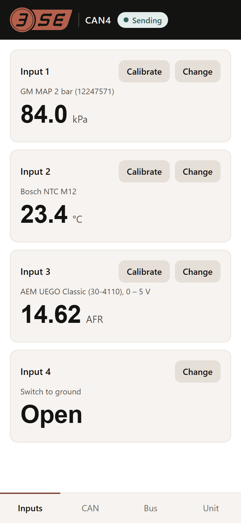
One card per input, numbered as the sensor cables are. Each shows the sensor chosen, tagged calibrated or smoothed when it is, the live reading, and a line under it when the reading is not good:
| The card says | What it means |
|---|---|
| Below its range | The reading is below what the sensor gives in use: often an open wire or an unplugged sensor. The input sends its failed-input value. |
| Above its range | The reading is above what the sensor gives in use: often a signal shorted to 5 V, or a thermistor's wire shorted to ground. The input sends its failed-input value. |
| Something drives this input; choose a voltage sensor or check the wiring | The input is set to a thermistor or switch, and something is putting a voltage on its wire. The module will not switch its pull-up onto a driven wire. Choose a voltage sensor if one is connected, or check the wiring. |
| The input converter did not answer | The module could not read the input. Power the module off and on; if it stays, contact us. |
A switch reads Open or Closed. An input set to Not used shows a dash. Readings are shown in the units chosen on the Unit tab, metric or imperial; the bus always carries metric.
Change
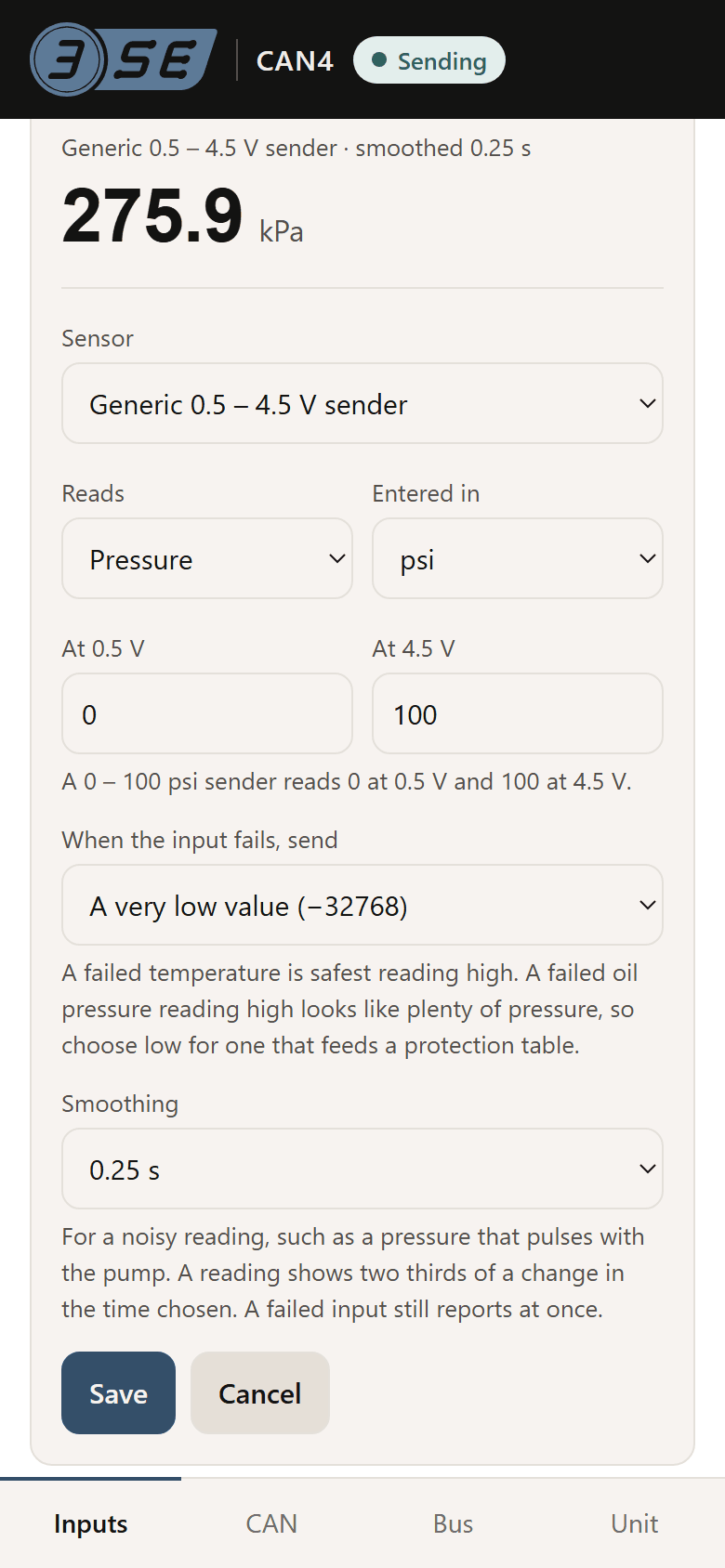
Change opens the input's settings. Sensor is a list of presets in five groups; choosing one sets the input's mode and the unit it sends.
| Group | Sensors | Sends |
|---|---|---|
| Voltage | 0 – 5 V, read as volts. A new unit's inputs are all set to this | Volts |
| Pressure | Generic 0.5 – 4.5 V sender; GM MAP 2 bar (12247571); GM MAP 3 bar (12223861), unverified | The generic sender: what you choose. The MAP sensors: kPa |
| Wideband | AEM X-Series UEGO (30-0300), 0.5 – 4.5 V; AEM UEGO Classic (30-4110), 0 – 5 V; Innovate LC-2, factory 0 – 5 V output, unverified | Air-fuel ratio |
| Temperature | Bosch NTC M12; GM / Delphi coolant or air; generic 10 kΩ thermistor, β 3950 | °C |
| Other | Switch to ground; Custom voltage scale; Custom thermistor curve; Not used | A switch: 0 open, 1 closed. The custom ones: what you choose |
A preset marked unverified is built from published figures not yet checked against the sensor: calibrate it against a known value before relying on it. The bus units and their scales are in the datasheet: temperature in 0.1 °C, pressure in 0.1 kPa, voltage in 1 mV.
A thermistor, a switch or a custom thermistor curve switches the input's pull-up on. Choosing one asks first: Use this input for a thermistor or switch? A 0 – 5 V sensor on an input with its pull-up on reads wrong. The module checks the wire before it switches the pull-up on, and leaves it off if something is driving it.
Three choices open fields of their own:
- Generic 0.5 – 4.5 V sender
- Reads is the quantity: pressure, temperature, voltage, AFR, lambda or percent. Entered in is the unit you type the two values in, kPa, psi or bar for a pressure and °C or °F for a temperature. At 0.5 V and At 4.5 V are what the sender reads at each end: a 0 – 100 psi sender reads 0 at 0.5 V and 100 at 4.5 V. The two must differ.
- Custom voltage scale
- For any linear 0 – 5 V signal, such as a separate EGT amplifier or a wideband controller's analog output. Reads and Entered in as above, then two points from the sensor's datasheet: At this voltage and It reads, twice, at least 0.05 V apart with two different readings. Fault below (V) and Fault above (V) are where the input is taken as failed; the first must be the lower. Powered from says whose 5 V the sensor runs on: This module's 5 V for a sensor on its cable's red conductor, whose reading then follows the module's measured 5 V, or Its own supply for a controller or amplifier powered separately, whose does not.
- Custom thermistor curve
- For a thermistor with no preset. Enter three points from the sensor's resistance table, spread across its range: Ohms and the temperature it is At, in the unit chosen in Temperatures in. Resistance must fall as temperature rises, and the page refuses three points no thermistor curve passes through. Fault below and Fault above are the temperatures outside which the input is taken as failed.
Changing a unit while values are typed converts them: 100 psi becomes 689.5 kPa, not 100 kPa. A number can be typed with a point or a comma as its decimal mark.
Two more settings apply to every sensor:
- When the input fails, send
- A very high value (32767), the default; A very low value (−32768); or The last good reading, which is the high value until there has been one. The status frame says why the input failed. A failed temperature is safest reading high. A failed oil pressure reading high looks like plenty of pressure, so choose low for one that feeds a protection table.
- Smoothing
- Off by default, or 0.1, 0.25, 0.5, 1, 2 or 5 seconds: the time a reading takes to show two thirds of a change. For a noisy reading, such as a pressure that pulses with the pump. A failed input still reports at once. Not offered for a switch or an input set to Not used.
Save applies the input's settings at once; Cancel drops the edits. Changing the sensor or its values clears that input's calibration, and the page says so before you save.
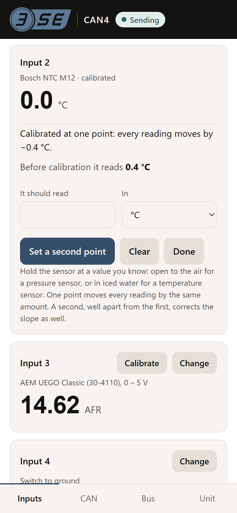
05Calibrate
Calibrate is on each card set to a voltage sensor or a thermistor; a switch and an input set to Not used have none. It corrects a reading against one you know, and works on top of the sensor's settings.
- Hold the sensor at a value you know: a pressure sensor open to the air, which an absolute sensor such as a MAP reads as the day's air pressure and a gauge sender as 0; a temperature sensor in iced water, at 0 °C. Before calibration it reads shows the reading the sensor's settings give.
- Type what it should read in It should read, choose its unit in In, and press Set this point. The page says what the input read there and what it reads now.
- For a second point, hold the sensor at a second known value well apart from the first and press Set a second point.
- Done closes the panel. The calibration is kept.
One point moves every reading by the same amount. Two correct the slope as well. The panel says which the input has: Calibrated at one point: every reading moves by …, or the two points and what each now reads. Clear forgets the calibration, after asking, and the input reads as its sensor settings give it again. A point cannot be set while the input has no steady reading.
06CAN tab
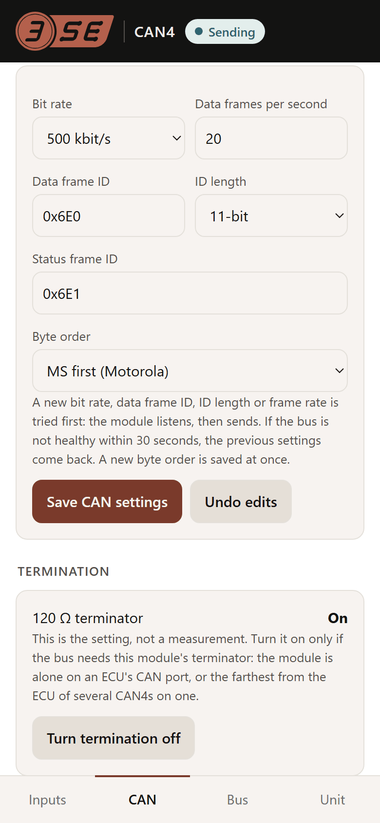
CAN settings
| Setting | What it is | Default |
|---|---|---|
| Bit rate | The bus's rate, 50 kbit/s to 1 Mbit/s. It has to be the rate the bus already runs at | 500 kbit/s |
| Data frames per second | How often the data frame goes out, 1 to 200 | 20 |
| Data frame ID | The data frame's identifier, typed as hexadecimal with 0x, like 0x6E0, or as decimal, like 1760. An ID with letters in it needs the 0x | 0x6E0 |
| ID length | 11-bit, standard, or 29-bit, extended | 11-bit |
| Status frame ID | Not set on its own: it is always the data frame's ID plus one, and shows where an edited data frame ID would put it | 0x6E1 |
| Byte order | MS first (Motorola) or LS first (Intel), for every value in every frame | MS first |
Save CAN settings sends only what changed, and asks first, listing it. A new bit rate, data frame ID, ID length or frame rate is tried before it is kept: the module stops sending, listens, then sends with the new settings, and if the bus is not healthy within 30 seconds the old settings come back. So make these changes with the module on the bus and the ECU on. A new byte order applies at once. Undo edits drops edits not yet saved; it does not undo a saved change.
Termination
Shows whether the module's 120 Ω terminator is on or off. This is the setting, not a measurement. The button turns it the other way, after asking. Turn it on only when the module is alone on an ECU's CAN port, or the farthest from the ECU of several CAN4s on one. A third terminator on a shared bus can upset engine management, and a missing one often shows up only once the car is hot.
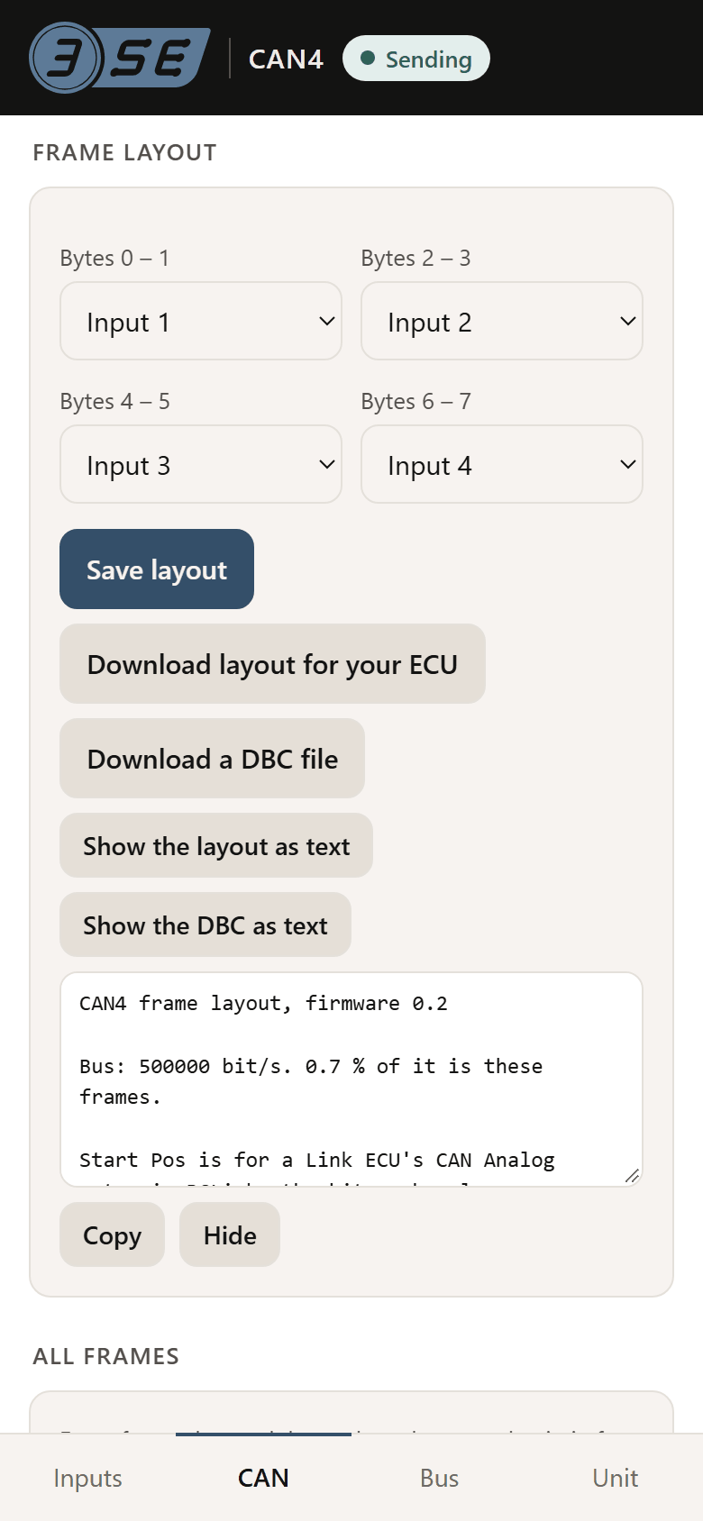
Frame layout
The data frame carries four readings in four pairs of bytes: Bytes 0 – 1, 2 – 3, 4 – 5 and 6 – 7. Each pair can carry any of Inputs 1 to 4, Input 1 in bytes 0 – 1 and so on by default. Save layout applies at once.
- Download layout for your ECU saves
can4-can-layout.txt: every frame and value as the module is set now: each value's bytes, width, sign, byte order and scale, and its Start Pos for a Link ECU's PCLink. - Download a DBC file saves
can4.dbc, for a logger or software that imports one. A DBC counts start bits its own way, so take PCLink's Start Pos from the layout file, not the DBC. - Show the layout as text and Show the DBC as text show the same text on the page, with Copy and Hide, for a window where a download does nothing.
07All frames
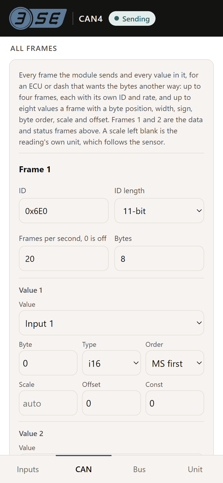
Under the frame layout, Edit the frames opens every frame the module sends and every value in it, for an ECU or dash that wants the bytes another way. Most setups never need it.
There are four frames. Frame 1 is the data frame and frame 2 the status frame; frames 3 and 4 are off by default, and start on 0x6E2 and 0x6E3, the second module's pair, so give them identifiers outside the modules' pairs before turning them on. Each frame has:
- ID and ID length, as in the CAN settings. Two frames in use cannot share an ID.
- Frames per second, 0 is off: how often the frame goes out, up to 200.
- Bytes, the frame's length, 1 to 8.
Each frame holds up to eight values, one row each:
| Column | What it sets |
|---|---|
| Value | What the value carries: an input's reading, an input's state, the flags, a counter that steps by one each time the frame is sent, the firmware's major or minor version, the measured 5 V rail, a constant, or Not used |
| Byte | The byte it starts at, 0 to 7. A value cannot run past the end of the frame or share a byte with another |
| Type | u8, i8, u16 or i16: unsigned or signed, 8 or 16 bits |
| Order | MS first or LS first, for this value alone. The byte order in the CAN settings sets every value's at once |
| Scale | Counts per unit: the value sent is the reading times the scale, plus the offset. Left blank, it is the reading's own scale, which follows the sensor: 10 for 0.1 °C, 1000 for 1 mV |
| Offset | Counts added after the scale, or blank for none |
| Const | The number sent, 0 to 65535, when the value is a constant |
Under the frames the page gives the share of the bus they take at the current bit rate; the module allows up to 30 %. Save frames asks first when an ID, rate or length changed: those are tried before they are kept, as a new bit rate is, and a changed value applies at once. If the module refuses an edit, the page says which frame and value, and keeps the edits not yet saved. Undo edits reloads the frames in use.
08More than one module
Each CAN4 on a bus needs its own pair of identifiers. On each added module's CAN tab, with it spliced onto the bus and the ECU on, set the data frame from the table below and save; the status frame follows. On a bus not at 500 kbit/s, set the bus's bit rate in the same save.
| Module | Data frame | In decimal | Status frame |
|---|---|---|---|
| First | 0x6E0 | 1760 | 0x6E1 |
| Second | 0x6E2 | 1762 | 0x6E3 |
| Third | 0x6E4 | 1764 | 0x6E5 |
| Fourth | 0x6E6 | 1766 | 0x6E7 |
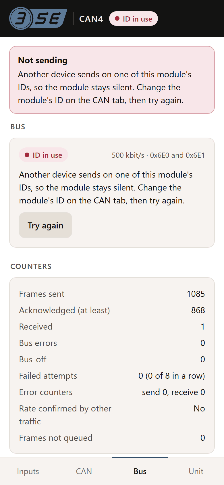
Two CAN4s on the same identifiers cannot both send: one that hears another on its identifiers stops, and either can be the one, or both. After the move, press Try again on the Bus tab of any module that still shows ID in use, or switch the ignition off and on.
09Bus tab
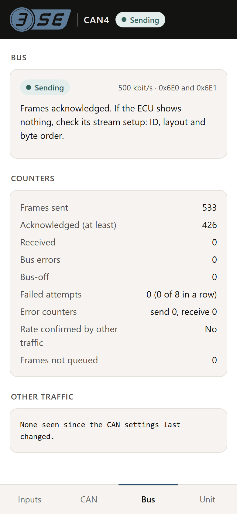
The bus from the module's side. The chip at the top says what it is doing, with the bit rate and its two identifiers beside it:
| Chip | What the module is doing |
|---|---|
| Listening | Listening before it transmits, as it does at power-on and after any bus change |
| Starting | Transmitting, and waiting for the first acknowledgement |
| Sending | Its frames are acknowledged: the bus is healthy |
| Waiting to retry | Its frames failed, so it has gone quiet and will try again, waiting longer each time; the advice gives the time to the next try |
| Stopped | It stopped after eight failed tries, and stays quiet until Try again or a power cycle |
| ID in use | Another device sends on one of its identifiers, so it stays quiet |
Under the chip, a line of advice says what to check:
- Bus errors while listening: the bus is probably at another bit rate
- The module will not transmit until it hears clean traffic. Set its bit rate to the bus's on the CAN tab, or the ECU's CAN port to the module's.
- Nothing acknowledged the module's frames, and no other traffic was seen
- Check that the ECU is on and its CAN port enabled, that CAN H and CAN L are not swapped, and that no wire is open.
- Frames failed with other traffic on the bus
- Check the bit rate and the termination.
- Frames are acknowledged and no other traffic is seen
- That looks like a port of its own. If the module is alone on the ECU's CAN port, the bus needs its terminator: turn termination on.
- Frames acknowledged. If the ECU shows nothing, check its stream setup
- The bus is fine; the ECU's setup is not reading the frames. Check the identifier, the layout and the byte order against the CAN tab.
Try again shows when the module is Stopped or its ID is in use, and starts it listening again.
Counters
| Counter | What it counts |
|---|---|
| Frames sent | Frames the module has transmitted |
| Acknowledged (at least) | Frames something on the bus acknowledged. A lower bound: it can trail Frames sent with nothing lost |
| Received | Frames from other devices it has heard |
| Bus errors | Errors seen on the bus |
| Bus-off | Times the module's CAN controller took itself off the bus after too many errors |
| Failed attempts | Tries to start sending that failed, with how many in a row out of the eight allowed before it stops |
| Error counters | The CAN controller's own send and receive error counts. They climb with errors and fall with good frames; near 0 is healthy |
| Rate confirmed by other traffic | Yes once it has heard clean frames from another device at its bit rate |
| Frames not queued | Frames the module had no room to send. Above 0, lower the frame rates or raise the bit rate |
Other traffic
The identifiers the module has heard from other devices since its CAN settings last changed, up to eight, each with its count, and a count of frames on any others. It shows what else is on the bus, and which identifiers are taken.
10Unit tab
Firmware
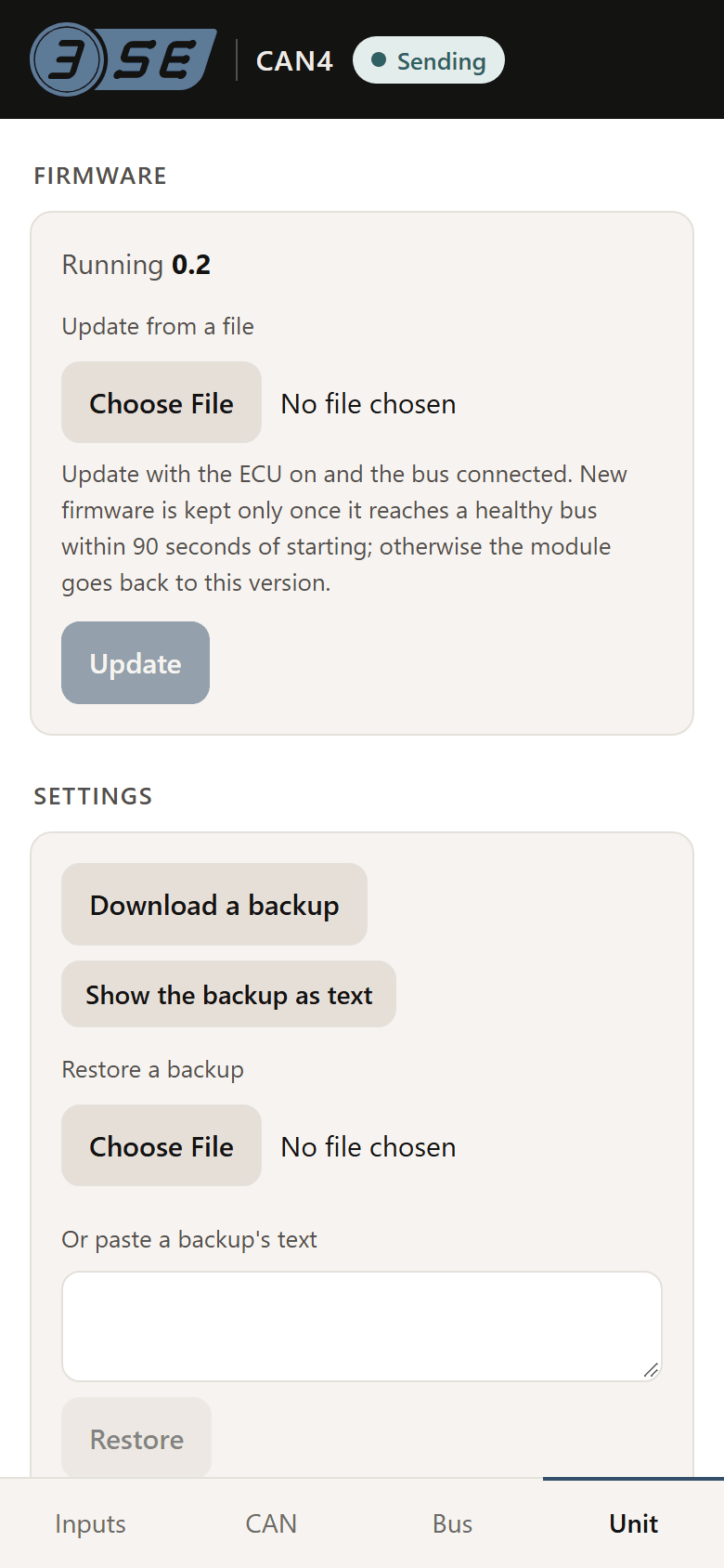
Shows the version running. To update:
- Open the page in Safari or Chrome rather than the sign-in window, with the ECU on and the bus connected.
- Under Update from a file, choose the firmware file, then press Update. The page asks first, with the file's name and size.
- If the bus is not healthy, the page asks Send it anyway? The new firmware has to reach a healthy bus within 90 seconds of starting, so turn the ECU on first if you can.
- If the file is older than the version running, or its version cannot be read, the page asks Install this version? with both versions.
- The module restarts, stops sending for a few seconds, and its WiFi restarts too. Join it again to see whether the new version is kept: the message New firmware on trial shows until the bus is healthy, and the module goes back to the version before if it is not within 90 seconds.
A second update is refused while the first is still on trial. Where the file controls are hidden, Show the file controls anyway brings them back.
Settings
- Download a backup saves
can4-settings.txt: the bit rate, the termination, every frame and value, and every input's sensor, values, failed-input setting, smoothing and calibration. Show the backup as text shows it on the page to copy instead. - Restore a backup takes a backup file, or its text pasted under Or paste a backup's text. Restore says how many settings it holds and asks first. A bit rate, ID, ID length, frame rate or frame length it changes is tried first, as on the CAN tab. If the module refuses some lines, the page says how many and why the first was refused. A backup from one CAN4 restores onto another, which is the quick way to set up a second module, but change its identifiers afterwards.
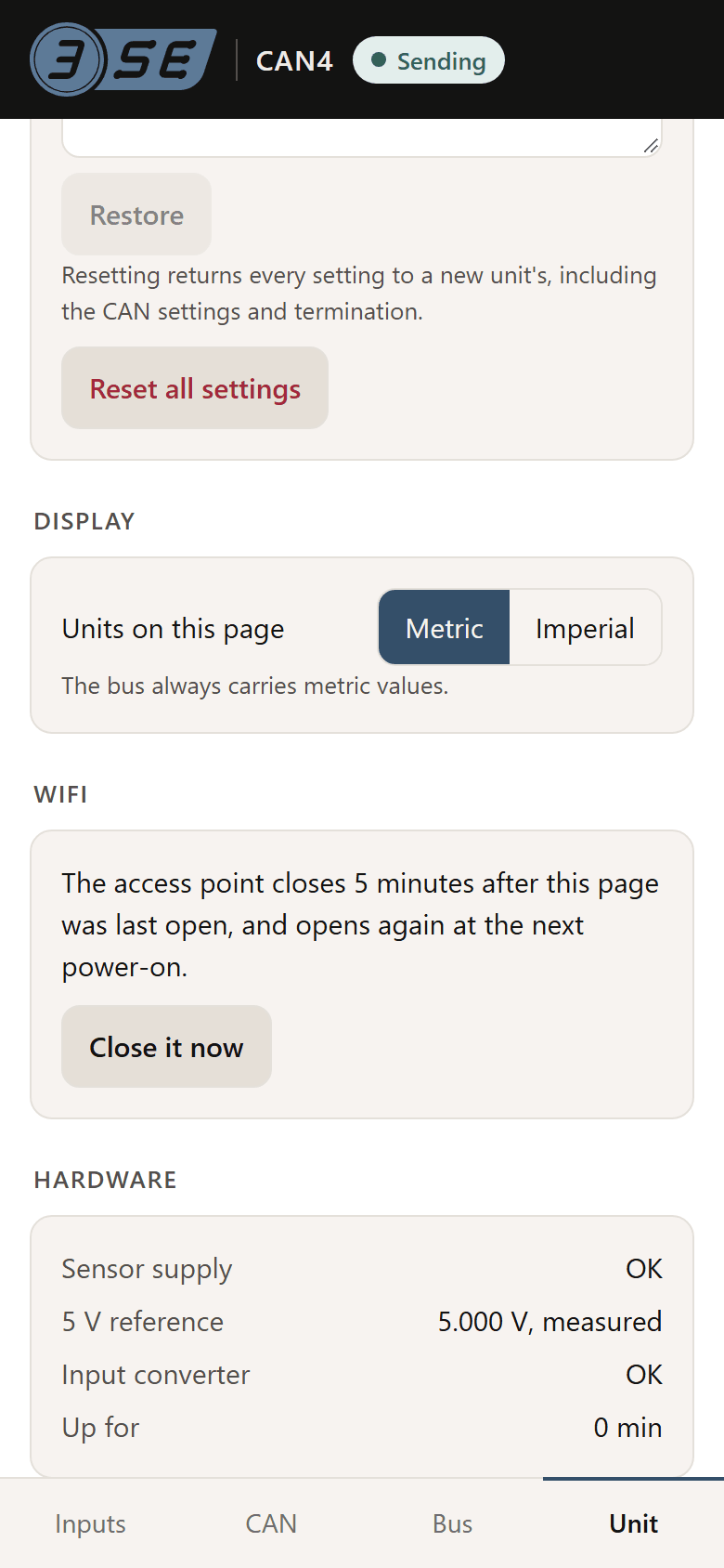
- Reset all settings returns every setting to a new unit's, after asking: every input to 0 – 5 V, read as volts, the CAN settings and frames to their defaults, and termination off, with the first-run question back. A bus setting the reset changes is tried first.
Display
Units on this page: Metric or Imperial, for the readings shown and the units offered when typing. It is kept by the browser, not the module, and the bus always carries metric values.
WiFi
The WiFi closes 5 minutes after the page was last open, and opens again at the next power-on. Close it now closes it at once, after asking; the page then stops, and the module carries on as it was.
Hardware
| Line | What it shows |
|---|---|
| Sensor supply | OK, or Tripped while a sensor's 5 V is shorted |
| 5 V reference | The module's own 5 V, measured, which every reading is worked out against. If it has not been measured lately the line says so, and 5 V is assumed |
| Input converter | OK. If it says the readings come in coarse steps, contact us |
| Up for | Minutes since the module last started |
Troubleshooting
- The network is not in the phone's list
- The WiFi has closed: it is up for 5 minutes after power-on. Switch the ignition off and on. If it still does not show, check the module's 12 V feed and fuse.
- The phone joins but the page does not open
- Go to
192.168.4.1in the browser. On Android, tap the network's sign-in notification or turn mobile data off. - The page says No answer from the module
- The phone has left the module's WiFi, often for another network it knows, or the WiFi has closed. Rejoin it.
- A download does nothing, or there is no file control
- The page is open in the phone's sign-in window. Show the text and copy it, or open
http://192.168.4.1in Safari or Chrome. - Every bus change is undone after 30 seconds
- Nothing acknowledged the new settings: the ECU is off, its CAN port is at another rate, or the module is on the bench with nothing else on the bus. Make bus changes with the module on the bus and the ECU on.
- An input reads Something drives this input
- It is set to a thermistor or switch with a voltage on its wire, as a 0 – 5 V sensor gives. Choose the voltage sensor it is, or check that the sensor is on the input you think.
- A reading is steady but a little off
- Calibrate it at a value you know, 05. A thermistor reading a few degrees out when cold may also be the 5 V reference not being measured: see the Hardware lines on the Unit tab.
- Readings are right on the page and wrong in the ECU
- The ECU's setup: the identifier, the start positions, the byte order or the scale. Compare it with Download layout for your ECU on the CAN tab, and see the setup guide for your ECU.
Specifications, wiring and the frame layout are in the datasheet (PDF); the headline specs are on the CAN4 page, and an overview of the setup page is here. Guides for each ECU are listed here.
The CAN4 isn't on sale yet. Leave your email on the store page to hear when it ships.