4 analog inputs · CAN 2.0B out
CAN4 specifications
Four engine sensors on the CAN bus. Each input takes a 0 – 5 V sensor, a thermistor or a switch, chosen on its setup page, and the module sends the reading in its unit: pressure, temperature, air-fuel ratio, voltage or a switch state. It wires in with five cable pigtails, and is set up from its own WiFi page in a phone's browser. There is no app; a laptop's browser works too, but is not needed.
Setup
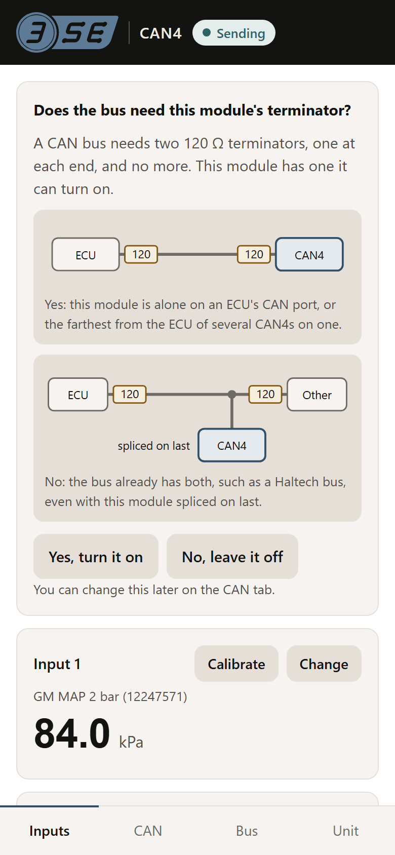
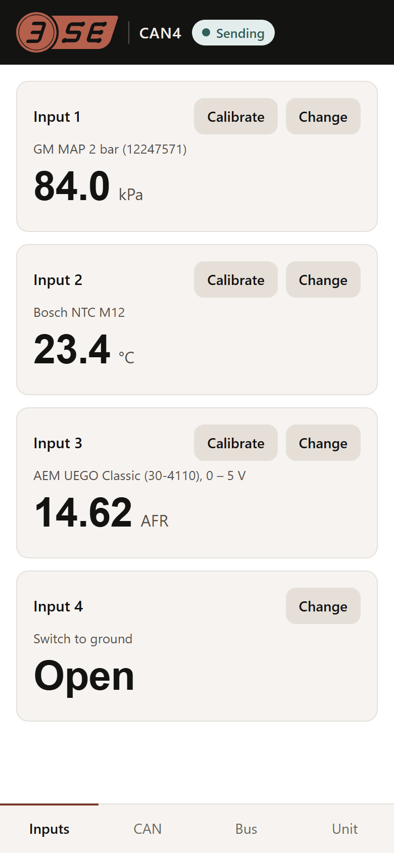
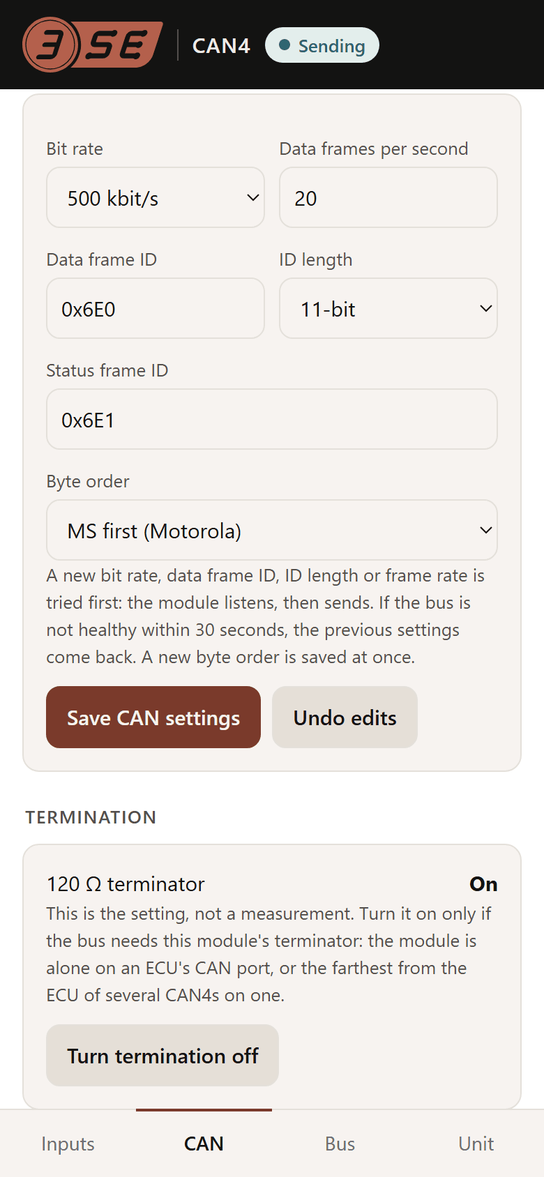
See every screen, and how the page works: its own network and password, and firmware updates over the same page.
Specifications
CAN4| Parameter | CAN4 |
|---|---|
| Inputs | 4, each set to 0 – 5 V, thermistor or switch from the setup page |
| 0 – 5 V mode | 0 – 5 V, 20 kΩ input, 16-bit conversion, 0.25 mV per count |
| Thermistor mode | 10 kΩ 0.1 % pull-up to the module's own 5 V, switched in per input. Curves for the Bosch NTC M12 family, GM/Delphi coolant and air temperature sensors, a generic 10 kΩ NTC, or a three-point custom curve |
| Switch mode | Open or closed, to ground |
| Presets | 0 – 5 V, read as volts · generic 0.5 – 4.5 V sender · GM MAP 2 bar (12247571) · GM MAP 3 bar (12223861), unverified · AEM X-Series UEGO (30-0300), 0.5 – 4.5 V · AEM UEGO Classic (30-4110), 0 – 5 V · Innovate LC-2, factory 0 – 5 V output, unverified · Bosch NTC M12 · GM / Delphi coolant or air · generic 10 kΩ thermistor, beta 3950 · switch to ground · custom voltage scale · custom thermistor curve. Unverified: built from published figures not yet checked against the sensor |
| Refresh | Frames up to 200 Hz each, set on the page; the bus load the module may take is capped at 30 %. Each input is read about 130 times a second with all four set to 0 – 5 V. With one set to a thermistor, that input is read about 35 times a second and the other three over 140. Inputs set to Not used are skipped, and the others are read more often. A frame sent more often than its inputs are read repeats their latest readings. Design values, not yet measured |
| CAN bus | CAN 2.0B, 50 kbit/s to 1 Mbit/s, 11-bit or 29-bit identifiers. 500 kbit/s by default |
| Frames | Up to four, each with its own identifier and rate. By default a data frame of four signed 16-bit readings at 0x6E0, 20 Hz, and a status frame at 0x6E1, 5 Hz. Every value's position, width, sign, byte order and scale is a setting |
| Byte order | MS byte first by default, LS first selectable, per value |
| Termination | 120 Ω on board, switched from the setup page, off until first-run setup asks |
| Bus safety | Silent at power-on, and listens before it transmits. It does not transmit while it hears bus errors, as traffic at another bit rate gives. On a silent bus it transmits on probation, backs off if nothing acknowledges it, and stops after eight tries. It goes quiet on an identifier another device is sending. Firmware design, not yet tried on a bus |
| On one bus | Several modules, each on its own pair of identifiers: the first at 0x6E0 and 0x6E1, the second at 0x6E2 and 0x6E3, moved on its setup page. At its defaults each takes under 1 % of a 500 kbit/s bus |
| Setup | The module's own WiFi setup page, in a phone's browser. No app and no cable; a laptop's browser works too, but is not needed. Tried on one iPhone so far, on a development board |
| Supply | 8 – 16 V switched, 12 V nominal. Starts above about 7 V; resets below about 6 V, as during a cold crank, and is back on the bus a few seconds after the engine catches |
| Sensor supply protection | Survives a short to ground and a short to battery, and recovers when the fault clears. Design values, not yet tested |
| Component rating | −40 to +105 °C |
| Size | 73.5 × 56 × 18.1 mm, 88.3 mm long over the zip-tie saddles, ASA |
| Power and CAN cable | 300 mm, 4-core 22 AWG, black jacket, marked CAN: red 12 V, black ground, white CAN H, yellow CAN L. Ends not stripped |
| Sensor cables | Four, 300 mm, 3-core 22 AWG, black jacket, marked 1 to 4 on the cable and on the module: red 5 V, black ground, yellow signal. Ends not stripped |
| Connectors | None. ECU makers wire their CAN plugs differently, and sensors come with plugs of their own. Splice the cables in, or fit the connector your ECU or sensor takes |
These are design values and component datasheet figures. No unit has been built or tested yet: nothing here is a measured accuracy or a tested rating, and nothing has been characterised over temperature.
Setup guides: wiring and software setup for Link ECU and Haltech Nexus, written from each maker's documentation and not yet run on an ECU, and the frame layout in the datasheet for anything else that reads a user-defined CAN frame. What differs between ECUs, and the setting for each: CAN, and what differs between ECUs. Each of those settings is on the module's setup page.
Warranty and support
12 months, replaced, no questions asked.
Support: the question form on thirdshiftelectronics.com, or sales@thirdshiftelectronics.com. Include the ECU it is fitted to, and what the Bus tab shows.
Full terms: thirdshiftelectronics.com/policies