CAN4 · the setup page
Setup
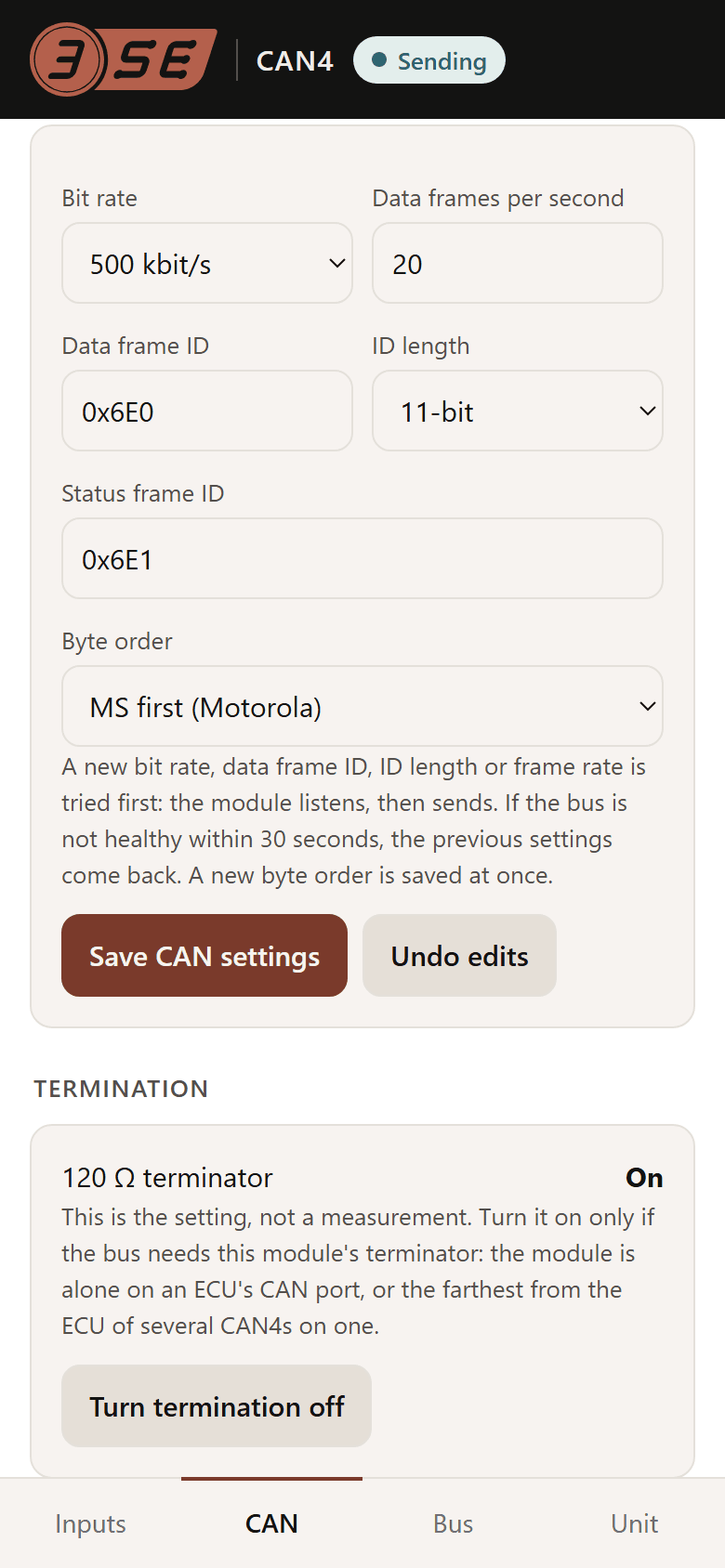
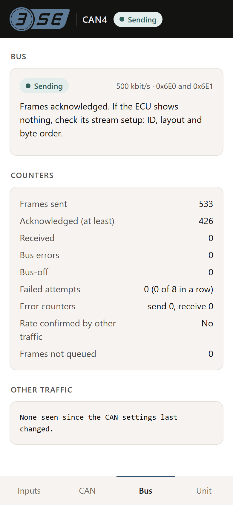
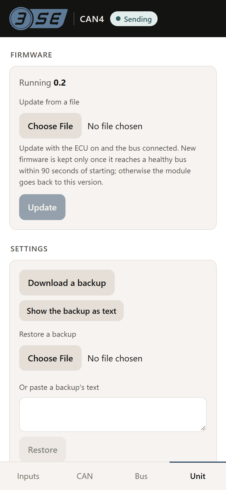
The module carries its own WiFi and its own page. Every setting an installer needs is on it: the bit rate, the identifiers, the byte order, what each input is wired to and what it should read. The page opens in a phone's browser, with no app and no cable; a laptop's browser works too, but is not needed. These are the page's own screens, drawn by the firmware a unit runs.
The page
First run, then four tabs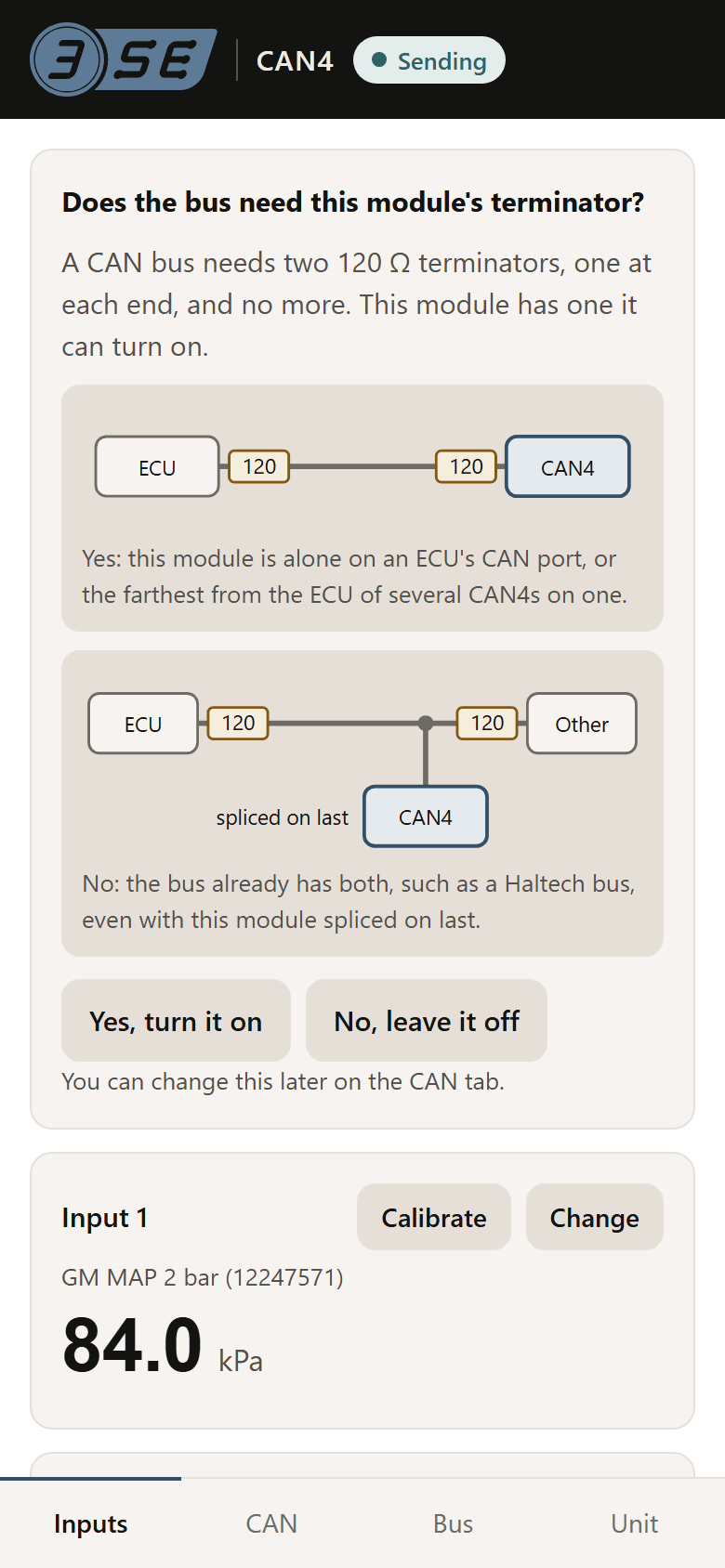
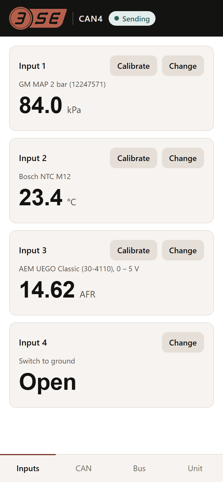
How it works
- Its own network. Power the module and its WiFi, CAN4- followed by four characters, is up for 5 minutes. It stays up while the setup page is open and for 5 minutes after, and the page can close it. If it has closed, switch the ignition off and on.
- Its own password. Each unit has one, WPA2, printed on its label.
- Nothing to install. The phone may open the page by itself when it joins the network. If it does not, open the phone's WiFi settings, or go to 192.168.4.1 in the browser. On Android, if the page does not open, tap the network's sign-in notification or turn mobile data off. It has been tried on one iPhone so far, on a development board.
- A bus change is tried before it is kept. A new bit rate, identifier, frame length or rate goes out on probation; if the bus never acknowledges it, the module undoes it after 30 seconds. Byte order, termination and value changes apply at once.
- Updates over the same page. A new firmware image that does not reach a healthy bus is undone automatically.
The EG5 and EG12 have no page. They are amplifiers: two calibration points in your ECU's own software, and the setup guides walk each platform through it.
What differs between ECUs, and the setting for each: CAN, and what differs between ECUs. The rest of the module: specs and wiring.